
Chamber balance
The equation V·dp/dt = Q − S·p is solved, so outgassing, leakage and process gas affect both time and attainable pressure.
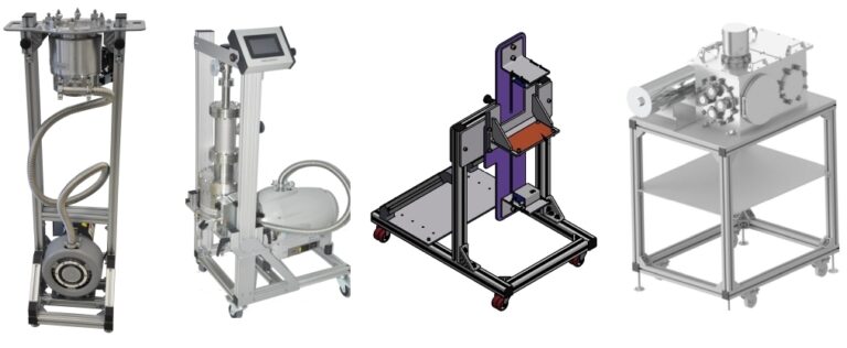
Preliminary sizing of actual pump speed from chamber data, process time, gas load, connection conductance and catalogue data.
Simple mode estimates the load from chamber material and seals. Advanced mode accepts measured system parameters and catalogue data.
The list is filtered by nominal speed, ultimate pressure and cleanliness requirements.
These are preliminary sizing examples, not a commercial offer. Before purchase, verify the exact variant, S(p) curve, connections, permissible foreline pressure and current availability.
The model separates transient pump-down demand from the steady gas load that limits final pressure.
The equation V·dp/dt = Q − S·p is solved, so outgassing, leakage and process gas affect both time and attainable pressure.
The full Knudsen equation varies conductance with pressure and distinguishes laminar, transitional and molecular flow.
Below 10⁻³ mbar, roughing and high-vacuum stages are sized separately, and the backing pump can also be checked against main-pump maximum throughput.
The nominal value is corrected by the actual speed fraction at the operating point, allowing comparison with a specific S(p) curve.
The model is based on relationships published by Leybold, Edwards and Kurt J. Lesker. Data for a specific pump must always be confirmed in its current manufacturer manual.
The calculator result is a starting point for selecting an architecture and catalogue models. Final sizing should account for the actual installation and manufacturer curves.
The essentials are chamber volume, initial and target pressure, required pump-down time, and connection diameter and length. A more accurate result also needs surface area, outgassing rate, leak rate and process load.
Pipework, valves, elbows and filters limit conductance, so only part of the pump’s nominal speed is available at the chamber. The narrower or longer the connection, the larger the difference.
No. This is preliminary sizing. Before purchase, verify the S(p) curve, ultimate pressure, maximum gas throughput, permissible foreline pressure, connections, process medium and material compatibility.
For high and ultra-high vacuum, the main pump, such as a turbomolecular pump, requires a backing pump. The calculator then separates evacuation from atmospheric pressure from the high-vacuum stage.